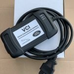







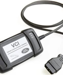


JLR VCI (D-PDU/J2534 PassThru) for SDD: The Essential Communication Bridge
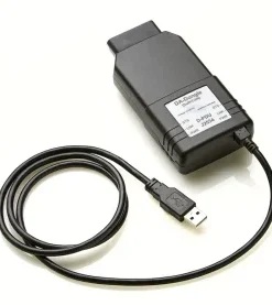
In the realm of Jaguar Land Rover (JLR) diagnostics, the distinction between a successful programming session and a costly module replacement often hinges on a single, critical piece of hardware: the Vehicle Communication Interface (VCI). For technicians relying on the legacy SDD (Strategic Diagnostic Device) or Pathfinder system, the JLR VCI operating in D-PDU (Diagnostic Protocol Data Unit) or J2534 PassThru mode is the non-negotiable linchpin. It solves the fundamental problem of protocol translation, allowing a standard Windows laptop running SDD software to communicate with the vehicle’s myriad control modules using manufacturer-specific diagnostic protocols. Without the correct VCI, even the most skilled technician is effectively locked out of the vehicle’s systems.
Technical Architecture of the JLR VCI
The JLR VCI is far more than a simple OBD-II cable. It is an intelligent gateway that facilitates communication between the diagnostic software on a PC and the vehicle’s network of Electronic Control Units (ECUs). Its operation is defined by two key standards:
J2534 PassThru and D-PDU API Modes
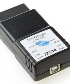
SDD primarily utilizes the J2534-1 PassThru standard, a SAE/ISO-mandated API that allows diagnostic applications to send and receive ISO 14229 (UDS) and other standardized messages through a compliant interface. The VCI acts as the physical layer, handling the conversion of these API calls into the specific voltage-based network signals (e.g., CAN High/Low, K-Line).
For more advanced or older vehicle communications, SDD may employ the D-PDU API, a precursor and functional complement to J2534. The critical factor is that a true JLR VCI is engineered and calibrated to support JLR’s precise timing requirements and proprietary protocol implementations beyond the basic SAE standards, ensuring reliable flash programming and module initialization.
Hypothetical Workflow: Module Replacement with SDD
Consider the standard procedure for replacing a Body Control Module (BCM) on a 2014 Range Rover Sport:
- Hardware Setup: Connect a stable power supply (>70A) to the vehicle. Connect the JLR VCI to the vehicle’s DLC and to the technician’s laptop via USB.
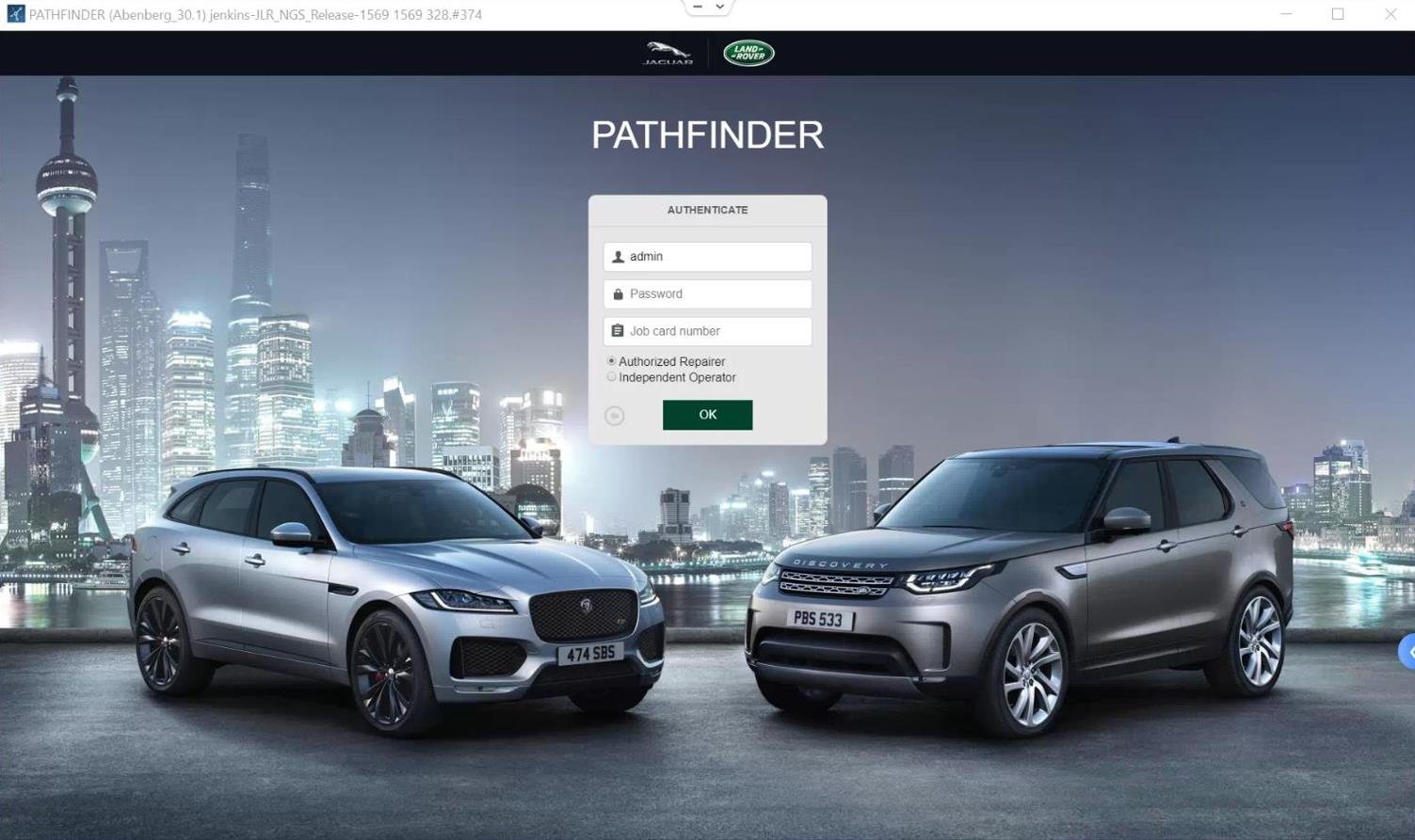
- Software Initialization: Launch SDD/Pathfinder. The software identifies the connected VCI via its drivers and establishes a J2534 connection.
- Vehicle Identification: SDD reads the VIN and connects to the diagnostic session, querying all modules. The VCI facilitates this broadcast communication across the vehicle’s CAN networks.
- Module Programming: Following the “replace module” routine, SDD prepares a software package. The VCI manages the high-speed, error-checked data transfer during the flash programming process, adhering to strict timing parameters.
- Configuration & CCF Coding: SDD writes the virgin module’s Car Configuration File (CCF) and performs necessary adaptations. The VCI transmits the large, block-by-block CCF data reliably.
Required Toolchain for SDD Operations
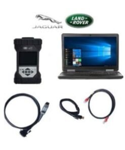
A complete SDD workstation requires an integrated system:
- JLR-Compliant VCI: The core component. It must be a dedicated JLR VCI with certified firmware for SDD compatibility. Generic J2534 boxes frequently fail during critical programming steps. The JLR VCI from Topix Cloud is engineered for this specific purpose.
- Stable DC Power Supply: An absolute mandate to maintain system voltage during long flash procedures.
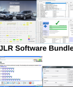
- SDD/Pathfinder Software: The legacy diagnostic application, configured with the correct vehicle data packs and calibration files.
- Technical Laptop: A Windows system meeting SDD’s specific requirements, with robust USB ports and all unnecessary services disabled to prevent communication interrupts.
Common VCI-Related Challenges and Mitigations
Technicians must be prepared to troubleshoot these common issues:
- “VCI Not Found” or Driver Errors: This is typically a PC configuration issue. Run the VCI manufacturer’s driver installer as Administrator. Manually assign COM ports in Device Manager if conflicts arise. Disable Windows power management for USB hubs.
- Communication Timeouts During Programming: Almost always caused by insufficient voltage or current. Verify the power supply is engaged and set correctly. Eliminate any USB hubs or extension cables; connect the VCI directly to a laptop USB port.
- Incomplete or Failed Flash Procedures: This can result from using a non-compliant, generic J2534 interface. A true JLR VCI handles the extended timing and packet sizes of JLR-specific flash routines. If failures persist, a different USB port or a full reboot of the laptop and vehicle systems is necessary.
- Protocol Selection Errors: While SDD usually auto-detects, forcing the wrong protocol (e.g., CAN vs. K-Line) via the J2534 API will cause a failure. Ensure the correct vehicle model and year are selected in SDD.
FAQ: JLR VCI for SDD
Can I use a generic J2534 PassThru device with SDD?
While some generic devices may partially function for basic diagnostics, they are not recommended for module programming or CCF writes. JLR’s software often uses proprietary extensions to the J2534 standard. A dedicated JLR VCI ensures compatibility, reliability, and safety during critical procedures.
Is this JLR VCI the same as the DOIP VCI used for TOPIx/JET?
No, they are different. The VCI discussed here uses USB and J2534/D-PDU APIs for SDD. The modern DOIP (Diagnostics over Internet Protocol) VCI uses Ethernet and a different software stack for the newer TOPIx cloud and JLR Engineering Tool (JET). They are not interchangeable.
Why is a power supply mandatory when using the VCI?
Module programming and CCF writing are high-current, long-duration operations. A vehicle battery alone cannot sustain the required voltage, and a dip below ~12.6V can corrupt the flash process, bricking the ECU. The power supply guarantees stable voltage, protecting both the module and the technician’s time.
Conclusion: The VCI as a Foundational Tool
The JLR VCI is the unsung hero of the JLR workshop. It is the critical, physical translation layer that makes advanced diagnostics and programming possible with SDD. Investing in a robust, purpose-built interface is not an expense but an insurance policy against communication failures that lead to vehicle downtime and expensive comebacks. Mastery of its setup and an understanding of its role within the J2534 framework are fundamental skills for any technician working on JLR vehicles from the late 2000s through the mid-2010s.
For technicians undertaking complex JLR diagnostic programming and authentic JLR OEM retrofits, possessing the correct factory-level tools is paramount. To source reliable VCIs and access expert technical support for these advanced tasks, the professional community relies on the resources available at jlrupgrades.com.