









Mastering Jaguar Land Rover’s All Terrain Progress Control (ATPC)
Technical Breakdown of All Terrain Progress Control (ATPC)
All Terrain Progress Control is a sophisticated subsystem. Specifically, it integrates within the vehicle’s broader Terrain Response 2 architecture. Its primary function is to maintain a pre-set speed (typically between 2 km/h and 30 km/h) in challenging off-road conditions, without driver intervention on the accelerator or brake pedals. This allows the driver to focus solely on steering.
System Architecture and Operation
ATPC does not operate in isolation. It is a networked function that relies on data from several key control modules:
- Anti-Lock Braking System (ABS) Module: Provides individual wheel speed data.
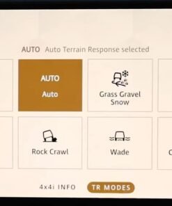
- Terrain Response Control Module: Sets the operational context based on the selected driving mode (e.g., Grass/Gravel/Snow, Mud/Ruts, Sand, Rock Crawl).
- Powertrain Control Modules (PCM/ECM): Manages engine torque and gear selection.
- Chassis Systems: Utilizes the stability control and traction control systems to modulate brake pressure at individual wheels to maintain traction and control speed.
The system’s logic constantly monitors for wheel slip. If it detects a loss of traction, ATPC can momentarily reduce torque or apply braking to the spinning wheel. At the same time, it redistributes drive to wheels with more grip. And it does all this while maintaining the set speed.
Hypothetical Activation and Configuration Process
Activating ATPC, especially on a vehicle where it was not originally specified or following module replacement, requires a deliberate and precise process using the JLR Engineering Tool (JET) within the TOPIx ecosystem.
- Vehicle Preparation: Connect a stable power supply to the vehicle to prevent voltage drop during programming. Connect a compliant DOIP VCI to the OBD-II port.
- Session Initiation: Launch JET via TOPIx cloud and establish a secure diagnostic session with the vehicle.
- CCF Navigation: Navigate to the CCF editing section for the central configuration module (often the Body Control Module or a dedicated vehicle configuration module).
- Feature Activation: Locate the ATPC-specific parameter blocks. These are typically found within the chassis/terrain response system menus. Change the ATPC status from ‘Disabled’ or ‘Not Fitted’ to ‘Enabled’.
- Dependency Checks: Ensure all system dependencies are correctly configured (e.g., Terrain Response 2 mode availability, correct ABS module software level).
- Configuration Write & Validation: Write the modified CCF back to the vehicle. Perform a full key-cycle and use the diagnostic session to read the CCF back, verifying that the changes have been accepted and stored correctly.
- System Function Test: Conduct a low-speed test in a safe, appropriate off-road environment to confirm ATPC engagement and operation.
Essential Tooling for ATPC Diagnostics and Programming
Attempting this procedure without the correct equipment will result in failure or, worse, vehicle module damage. The non-negotiable tools include:
- JLR-Approved DOIP VCI: A generic OBD-II interface is insufficient. A dedicated Diagnostics over Internet Protocol interface, such as the JLR VCI or a fully compliant third-party device, is mandatory for secure gateway access and module programming.
- Stable Power Supply: A 30-40A automotive power supply must be connected to the vehicle’s battery to maintain stable voltage during the CCF write process, preventing bus shutdowns.
- TOPIx / JET Subscription: Access to the TOPIx cloud platform with the appropriate security clearance for Engineering Tool operations is required to read and edit the CCF.
For technicians seeking a reliable and fully compliant solution for enabling features like All Terrain Progress Control, a dedicated interface is available. You can find the specific hardware and software package for ATPC here.
Common Challenges and Technician Solutions
Even with the right tools, technicians often encounter specific hurdles:
- “Configuration Incompatible” Error: This often indicates a missing software dependency or a conflict with another CCF setting. The solution is to ensure all related modules (ABS, Terrain Response) have the latest software calibrated and to meticulously check all associated configuration parameters.
- VCI Communication Timeouts: Unstable internet connection or a faulty/fake VCI can cause the DOIP session to drop. Use a wired internet connection and ensure your VCI is from a reputable source.
- System Engages but Cannot Maintain Speed: This is typically not a CCF issue but a mechanical or sensor-related fault. Diagnose using live data from the ABS module to check for erratic wheel speed signals or faults in the brake pressure sensors.
Frequently Asked Questions (FAQ) About All Terrain Progress Control
Can ATPC be retrofitted to any Land Rover or Range Rover?
No. Retrofitting ATPC is a complex OEM upgrade. Specifically, it is only feasible on vehicles originally equipped with the Terrain Response 2 system and the necessary hardware. These include the specific ABS module and chassis sensors. Importantly, this is not simply a software activation.
What is the primary difference between ATPC and standard Cruise Control?
Standard cruise control is designed for paved roads. Specifically, it maintains speed using primarily engine torque. In contrast, ATPC is for low-speed, low-grip environments. It uses the entire chassis system—including individual wheel braking and traction control—to maintain progress and manage wheel slip.
Why is a stable power supply critical during CCF editing?
A voltage drop below a critical threshold during a module write cycle can corrupt the module’s memory. This can lead to a “bricked” module that is inoperable and may require replacement, a costly and time-consuming error.
Conclusion
All Terrain Progress Control is a hallmark of JLR’s advanced off-road engineering. However, its functionality depends entirely on flawless vehicle configuration. For the professional technician, mastery of the JLR Engineering Tool, a compliant DOIP VCI, and a rigorous process is non-negotiable. Understanding the system’s architecture, the necessary tooling, and common pitfalls is the key to successfully diagnosing, activating, and repairing this complex system. Proper execution ensures first-time fixes and enhances customer satisfaction with these premium vehicles.
For reliable tools, expert support, and comprehensive guides for complex JLR diagnostic programming and OEM retrofit tasks like this, we recommend visiting our trusted resource at jlrupgrades.com.