
Technical Deep Dive: Activating JLR Auto High Beam Assist via CCF Editing
For professional Jaguar Land Rover technicians, mastery of the JLR Engineering Tool (JET) and advanced CCF (Car Configuration File) editing represents a critical step beyond basic diagnostics.
These skills enable controlled feature activation and OEM retrofit work, directly responding to customer demand for enhanced vehicle functionality while maintaining factory integrity.
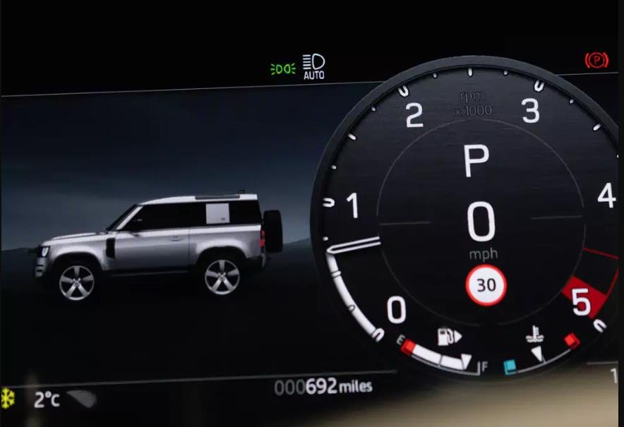
One of the most frequently requested lighting features is Auto High Beam Assist.
In many JLR platforms, the required hardware—particularly the forward-facing camera—is already installed from factory but disabled in software on lower specification models.
This guide provides a technical overview of how JLR Auto High Beam Assist operates, how it is enabled through CCF coding, the professional tools required, and the most common pitfalls technicians must avoid.
Technical Operation of JLR Auto High Beam Assist
JLR Auto High Beam Assist is an intelligent lighting function designed to maximize nighttime visibility without compromising the safety of other road users.
The forward-facing multi-function camera module, typically mounted behind the windscreen near the rear-view mirror, primarily governs the system logic.
This camera continuously analyses the road ahead, identifying light sources such as oncoming headlights, preceding vehicle tail lamps, and ambient lighting conditions.
Based on this data, the system dynamically determines whether high beam illumination is appropriate.
System Logic and Component Integration
When Auto High Beam Assist is enabled and the driver places the lighting stalk in the high beam position, control is handed over to the vehicle’s automation logic.
The camera module communicates detection data over the CAN network to the Headlamp Control Module (HCM).
Upon detecting an oncoming or leading vehicle, the system immediately commands the HCM to dip the headlights to low beam.
Once the detected vehicle has passed or moved out of range, the system automatically restores high beam operation.
This decision-making loop occurs within milliseconds and requires precise coordination between multiple control modules.
From a configuration standpoint, activation requires correct CCF configuration across several key modules:
- Body Control Module (BCM / BCFG)
- Instrument Cluster (IC)
- Forward-Facing Camera Module
Hypothetical Step-by-Step Activation Process
Disclaimer: This is a generalized technical outline. Always consult official JLR TOPIx documentation for vehicle-specific procedures.
- Pre-Diagnostic Scan and Hardware Verification
Connect a certified DOIP VCI (Vehicle Communication Interface) and perform a full vehicle network scan.
Confirm the presence and health of the camera module and HCM. - JET Session Initialization
Log in to TOPIx Cloud using a valid JLR TOPIx subscription.
Launch JET, enter the VIN, and establish a secure diagnostic session. - CCF Backup and Security
Read and save a complete backup of the original CCF before making any changes. - Configuration Editing
Modify configuration parameters in the BCM, Instrument Cluster, and Camera Module to enable automatic high beam logic. - Write and Validate
Write the updated CCF dat